Power and Energy-meter
Description of the power and energy-meter which I described during my talk "Solar-powering your geek gear". This device is well-suited for small solar-panels.
Introduction
Note: The author is not responsible for any damages of any kind done to anything by doing what is described here!
The measuring instrument that is described here has been developed for
solar applications. The device measures voltage, current and calculates
power as well as energy.
The devices powers itself from the input-voltage so no additional power-sources
(e.g. batteries) are needed. When the input-voltage drops below some
threshold, the energy-value is written to the EEPROM of the microcontroller
and restored at the next power-on.
Technical Specifications
- Voltage range: 10V - 25V
- Current range: 0A - 2A
- Power range: 0W - 50W
- Energy range: 0Wh - several Wh
Hardware
The hardware of the device consists of the following components:
- AVR micro-controller (AVR Atmega8)
- 5V voltage regulator (7805)
- LC-Display (HD44780 compatible)
- Operational amplifier (LM358)
- Some resistors and capacitors
The micro-controller is equipped with several analog inputs which can
be used to measure voltage and current.
The input voltage is measured directly
using a voltage divider and the current is measured using a small shunt of about 10 Milli-Ohm.
A current of 2A will thus cause a voltage-drop of about 20mV at the shunt. This voltage is amplified
by the operational amplifier and fed into the analog-digital-converter of the micro-controller.
This drop is acceptable - on the other side,
if no amplifier had been used but instead a 1Ohm-shunt, a current of 2A would cause a voltage-drop of two precious volts, which I consider is too much
for solar-applications.
The amplification of the OP-Amp is not perfectly linear, because of a missing
negative supply, but it should be enough for the targeted purpose of the device.
The display which displays the values
is connected to the controller using a 4-bit bus.
The voltage-regulator generates a voltage of 5V, the buffer-capacitor
behind the diode is sufficiently dimensioned so that after a sudden
voltage-drop at the input, there will be enough time to
save the current energy-value to EEPROM.
Schematics
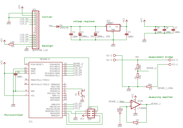
Large version
Eagle-File (via SVN): main.sch
Pictures
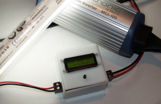
With an inverter and a CCFL as load:
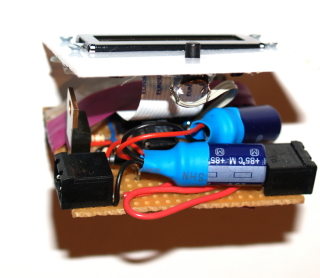
Inside the device:
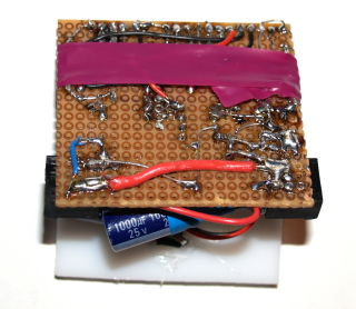
Back of the PCB:
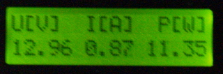
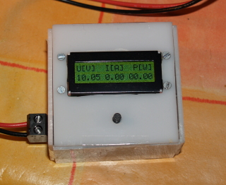
Default mode (shows voltage, current, power):
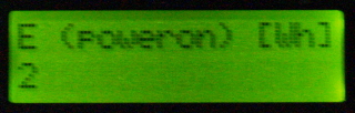
Energy since poweron:
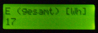
Overall energy:
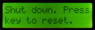
Powerdown mode:
Software
The following tasks are executed cyclic by the software:
- Measure the analog values
- Transform the values
- Calculate power (P=U*I) and energy (E=integral of power over time)
- Check whether shutdown is neccessary
- Respond to button presses (switch display, reset)
Shutdown
The purpose of the shutdown is to write the current energy-value safely
to EEPROM when the input-voltage drops below a critical threshold (about 9V).
As soon as this happend, the device will be in shutdown-mode. Even when the
input-voltage rises again, the device will not reactivate itself. This behavior prevents many EEPROM-writes when the input-voltage is unstable.
The device can be reset by pressing the button.
Download
The code can be obtained via anonymous SVN:
https://svn.scriptkiller.de/power_meter/tags/2008-12-24-25c3/src/
|
